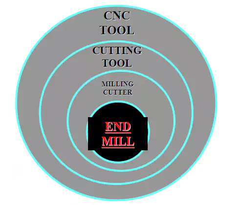
Milling cutter is used for slotting and machining precision appearance components on milling machine. Many things in our daily life can be made by milling process. If you don’t use these milling tools, it will cost a lot to produce those things. Things with only a few dollars may cost hundreds or even thousands of dollars to produce.
Milling machine is a machine tool with a wide range of uses. On the milling machine, plane (horizontal plane and vertical plane), groove (keyway, T-shaped groove, dovetail groove, etc.), toothed parts (gear, spline shaft, sprocket, spiral surface (thread, spiral groove) and various curved surfaces can be processed. In addition, it can also be used for machining the rotating surface, inner hole processing and cutting off, etc.,.
When the milling machine is working, the workpiece is mounted on the workbench or the accessories such as the indexing head, and the milling cutter rotation is the main movement, supplemented by the feeding movement of the workbench or milling head, so that the workpiece can obtain the required machining surface. Because it is multi-tool intermittent cutting, the productivity of milling machine is high.
The correct selection and use of end mill are essential for the entire processing process. There are many kinds of materials and design styles of end mills, which should be properly selected according to the specific operation. In addition, the cutter can also have various external coating layers, which can be used to prolong the life of the cutter, lower the operating temperature and and cool down.
It is very important that the tool should be tightly fixed on the tool holder. If the tool is not firmly fixed, it will make the cutting effect worse and unstable. The best fixing method is to install the tool on tool rack with the same center.

Basic Application Scope of End Milling Cutters
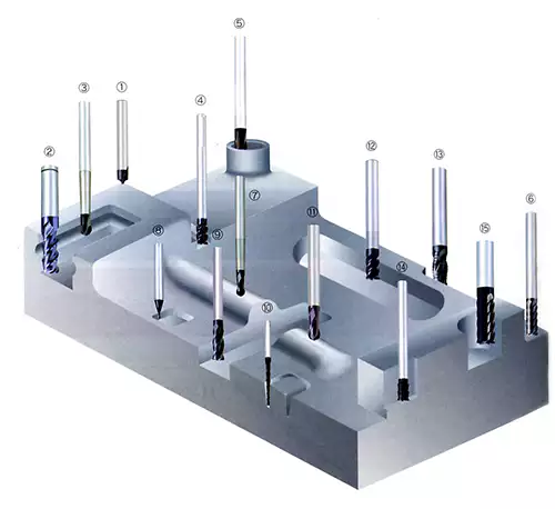
End face milling: applicable to the operation requirements of smaller plane range and smaller cutting depth. The surface of the processed parts is relatively rough and uneven.
Machining keyway: Generally speaking, it takes at least two milling cutters to produce a high-quality keyway.
Processing crescent keyway: Generally speaking, this process requires a milling cutter, which is operated by the overall feed method.
Special cutting: including the milling of conical surface (such as “T”-shaped groove) and the processing of dovetail groove.
Fine copying cutting: finish the contour of inner surface/outer surface on the workpiece with parallel side walls.
Mould hole processing: it roughly includes surface processing and fine processing in the concave of the steel mould. The processing of concave mold processing requires three-dimensional orientation. Ball milling cutter is more suitable for this operation.

Types of milling cutter processing
Milling: a directional milling operation. The cutting direction can be adaptive to the machining area, and the feed force is low. For this operation, the cutting tool produced by CNC should be the first choice, which has a long service life. This operation is also called “milling down”.
Conventional milling: a directional milling operation. The tool is easy to push the workpiece away from the processing area, and the feed force is high. Hand-made tools should be preferred for this operation. This operation is also called “milling up”.
End milling: the process of cutting the workpiece with a rotating tool. This operation is also called “vertical milling”
Peripheral milling: Machining the edge surface of parts. Use the peripheral part of the milling cutter to process the workpiece.
Cut-in grinding: the cutter is fed into the parts along the axial direction. The CNC machining machine processes in the direction of Z axis, cutting directly into the surface of the component, and the cutting direction is the axis direction. This operation requires a central cutting end mill.
Bevel cutting: feed parts in the axial direction. The CNC machining machine processes in the direction of Z axis and other axes (X and Y axes), and the angle of the surface of the cutting part is different from the direction of the axis. This operation requires a central cutting end mill. Bevel cutting can assist the end milling operation to enter the surface of parts.
Terminology of end mill
Oblique blade: A straight blade that makes an angle with the axis of the cutter. Oblique edge cutters are not as flat as spiral edge cutters.
Curvature: the difference between the maximum index and minimum index of the surface near the outer diameter of the tool.
Inverted taper: a slight taper, which is formed by the diameter of the shank being smaller than the diameter of the cutting end.
Cut surface: a slightly cushioned plane set on the periphery and outer surface of the cutter. Used to strengthen some weak places.
Chip breaker: a device with a special appearance on the cutter surface, which can make the chip curl tightly and break.
Chip dandruff: There are some small grooves around the end milling tool bar, which can cut narrower chips, and it is suitable for rough processing.
Cleared area: an area formed by removing excess tool materials after buffering corners.
Clearance angle (back angle): the tangent position of the clearance part and the angle formed by the blade.
Back angle (5-9 degrees of the first level angle): it can cushion the vicinity of the cutting edge.
Secondary angle (secondary angle is 14-17 degrees): it can cushion the vicinity of the cutting edge.
Three-level rear angle (three-level corner): provides buffer for the second-level corner.
Cutting edge: The main edge of the blade. It is formed by the intersection of two fine and sharp surfaces, and the formed slope angle is generally less than 90 degrees.
Cutting edge angle: the angle formed by the cutting edge and the cutter shaft.
Cutter groove: the area between the cutting edges for chip discharge and sharpening operation. The number of flutes is generally related to the number of blades, and the feed rate of the end mill depends on the number of flutes.
Slot length: the total length of the blade slot, which is often confused with the length of the flute, and is mistaken for flute length.
Flute length: the effective axial length of the peripheral blade.
Handle: an important part of the tool, which supports and drives the processing of the tool.
Technical Index Parameters of End Milling Cutter
Chip amount: the amount of material cut by each groove of the cutter.
Feed rate: the rate at which each cutting edge of the cutter enters the workpiece-inches/minute.
Inch per minute (IPM): the linear distance that the cutter enters the workpiece per minute, expressed in inches.
Cutting depth (DOC): the depth after the end mill enters the surface of the part in the axial direction. When milling with a computer numerical control machine, the Z-axis direction is usually taken as the standard.
Inch/revolution (IPR): the feed rate of the cutter per revolution. In inches, the feed rate of the cutter can be calculated with it.
I.P.R. = cutting amount x number of tool slots
Millimeter per revolution (MMPR): the feed rate of the cutter per revolution. In metric system, the feed rate of cutter can be calculated by it.
M.M.P.R. = cutting amount x number of tool slots
Meters per minute (MPM): the cutting speed of the end mill. This metric unit is applicable in all areas. The unit represents the rate at which the tool passes through the part.
Revolutions per minute (RPM): the running speed of the tool spindle, which can be calculated in MPM or SFPM units.
Surface Feet Per Minute (SFPM): This is the unit of cutting rate of end mills used in the United States. It represents the circumference of the cutter in a given position per minute, expressed in feet.
When using the cutting tool, choose the appropriate cutting speed, feeding speed and cutting depth.
Buyers must pay attention to the following parameters when using the end mill:
SFPM: cutting rate of tool surface
Chip amount: the amount of material cut by each groove of the cutter.
Cutting depth: selected according to specific parts.
Note: the cutting depth should not exceed the depth of the cutter groove, which will damage the cutter. If it is necessary to cut deeper, change the cutter with a larger diameter, and always keep the ratio of cutter diameter to cutting depth at 1:1.
Cutting width: the maximum should not exceed 2/3 of the cutter diameter.


